
Hardware Build for the Rose Engine Butler
This page covers building the Rose Engine Butler hardware: the base box and the optional expansion box. Once the hardware is built, continue with Software Installation and Setup.
|
The two boxes
|
|
|
Parts
For running REB, you will need:
| # | Item | Qty | Source | Source P/N | Comments |
| Base Box | |||||
| 1000 | Case | ||||
| 1001 | Case | 1 | |||
| 1100 | Power | ||||
| 1101 | Power Switch | 1 | Astrodyne TDI | 082M.01001.00-LS | |
| 1102 | Power Cord | 1 | Schurter | 6009.1214 | |
| 1103 | Power Outfeed Jack | 1 | Schurter | 6600.4315 | |
| 1111 | 24 VDC Power Supply | 1 | MeanWell | LRS 100-24 | |
| 1112 | 24 VDC to 5 VDC power module | 1 | Powers both the Raspberry Pi and the Mesa card. See the power note under Connections. | ||
| 1121 | 110 VAC power cable, #14 | 1 | |||
| 1122 | 24 VDC power cable, #26 | ||||
| 1200 | Electronics Inside the Box | ||||
| 1201 | Raspberry Pi 5
| 1 | CanaKit | PI5-8GB-STR128-C4-BLK | |
| 1210 | Mesa 7i92TH Anything I/O Ethernet card | 1 | Mesa US | 7i92TH | The base card. Its address is 10.10.10.10. |
| 1220 | Stepper Motor Drivers | 6 | Stepper Online | DM542T | Channels 00 - 05 |
| 1230 | REB PCB | 1 | |||
| 1240 | Ethernet switch, gigabit, unmanaged | 1 | Only the Raspberry Pi and the Mesa cards are connected to it. | ||
| 1300 | Panel Mount Parts | ||||
| 1301 | |||||
| 1400 | Cables within the Box | ||||
| 1401 | IDC26-IDC26 Ribbon Cable | 2 | |||
| 1402 | IDC6-IDC6 Ribbon Cable | 12 | 2 for each stepper motor driver | ||
| 1403 | Ethernet cable (CAT-6 or better) | 2 | Raspberry Pi to switch, and switch to the base card | ||
| Expansion Box (optional) | |||||
| 2000 | Case | ||||
| 2001 | Case | 1 | |||
| 2100 | Power | ||||
| 2101 | Power parts | To be confirmed | |||
| 2200 | Electronics Inside the Box | ||||
| 2210 | Mesa 7i92TH Anything I/O Ethernet card | 1 | Mesa US | 7i92TH | The expansion card. Its address is 10.10.10.11. |
| 2220 | Stepper Motor Drivers | 4 | Stepper Online | DM542T | Channels 06 - 09 |
| 2230 | REB PCB | To be confirmed | |||
| 2300 | Panel Mount Parts | ||||
| 2301 | GX-12 limit switch jacks | 3 | Limit Jacks 4 - 6 | ||
| 2400 | Cables within the Box | ||||
| 2401 | IDC26-IDC26 Ribbon Cable | 2 | |||
| 2402 | IDC6-IDC6 Ribbon Cable | 8 | 2 for each stepper motor driver | ||
| 2403 | Ethernet cable (CAT-6 or better) | 1 | Expansion card to the switch in the base box | ||
| Other | |||||
| 1900 | Other | ||||
| 1901 | Computer Monitor (1920x1080) | 1 | LG | 24MR400-B.AUSQ | |
| 1902 | Keyboard & Mouse | 1 | Kensington | K72436AM | |
|
|
Connections
The overall connections for this system are as shown to the right. The items in the blue box are shipped as the REB system. The boxes in gray and the associated cabling are optional.
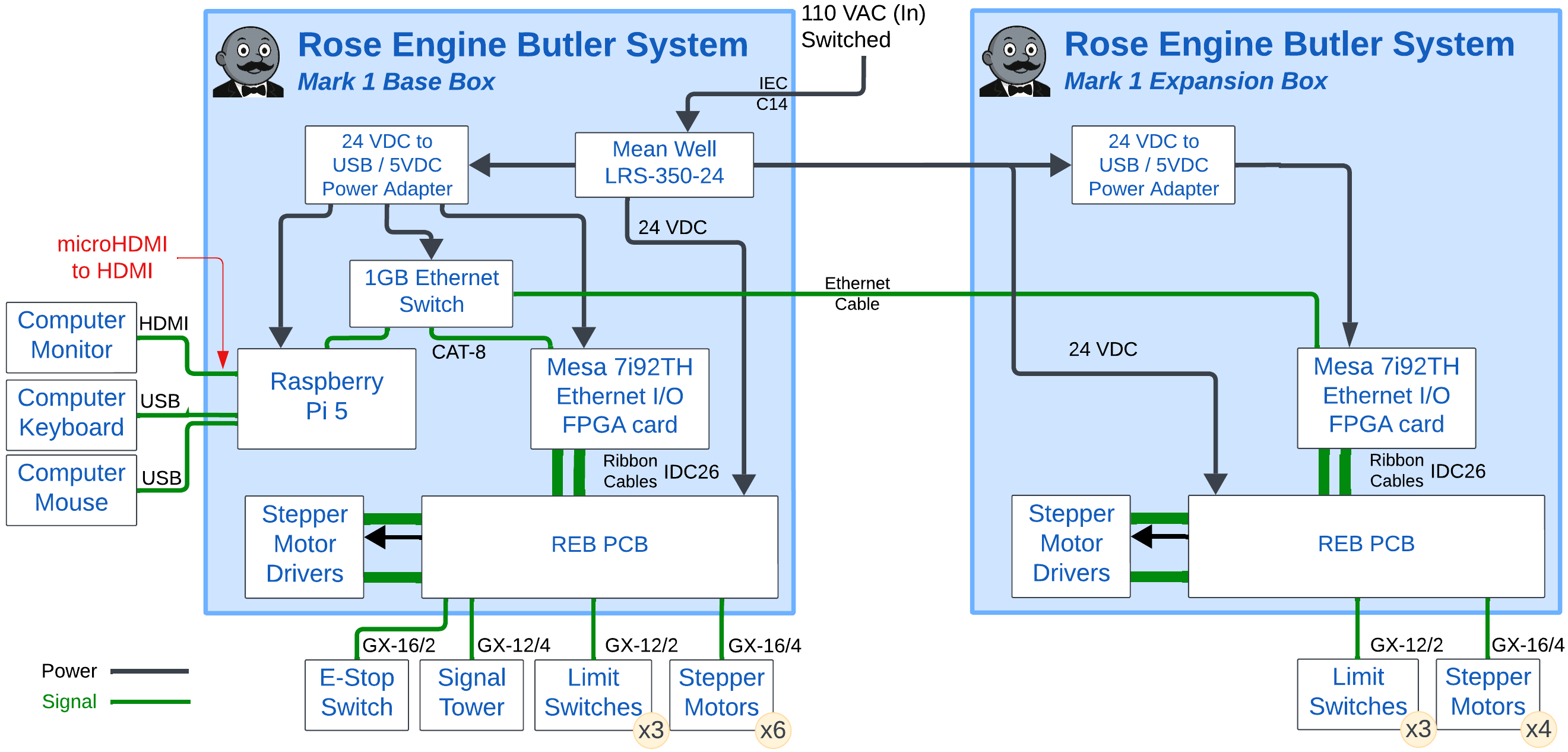
Overall Connections
The Wired Network
The Raspberry Pi and the Mesa cards talk to each other over a private wired network, through the Ethernet switch in the base box.
- Plug the Raspberry Pi, the base card and (if used) the expansion card into the switch.
- Nothing else goes on the switch - no router, no internet connection, no other computers. Other traffic on that network upsets LinuxCNC's timing. The Raspberry Pi reaches the internet over WiFi instead.
- The addresses used on this network are:
| Raspberry Pi | 10.10.10.100 |
| Base card | 10.10.10.10 |
| Expansion card | 10.10.10.11 |
Power
In the base box, one 24 VDC to 5 VDC power module powers both the Raspberry Pi and the base card. Switching the card on while the Raspberry Pi is running restarts the Raspberry Pi without shutting it down, which can damage its microSD card. Always switch the whole machine off and on together.
Development (8-channel) Boxes
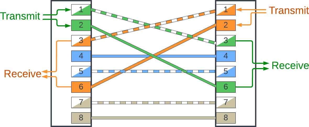
100 Mbit Ethernet Crossover Cable
The earlier 8-channel boxes are used as a base box: channels 00 - 05 work, and their other two plugs are not used. If the Raspberry Pi is wired straight to a single Mesa card (i.e., with no Ethernet switch) using an Ethernet crossover cable.
The wiring configuration for a 100 Mbit Ethernet crossover cable is shown to the right.
Pins 4, 5, 7, & 8 still need to be wired to make this cable work as expected.
There is no benefit to using a gigabit crossover cable.
|
|
Instructions
Part 1 - Configure the Hardware
1.1 DM542T Drivers
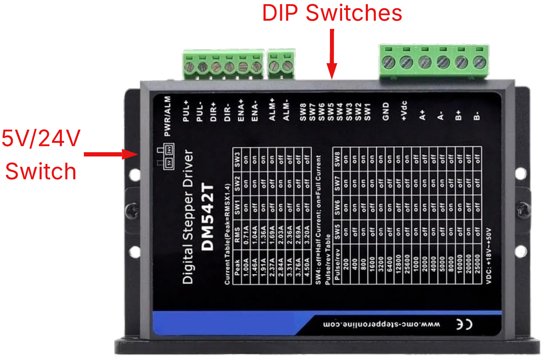
DM542T Driver
Configure each DM542T driver (6 in the base box, 4 in the expansion box)
- Set the voltage on the 5V/24V switch to 5V (that switch is located on the side of the DM542T, not the top where the DIP switches are).
- Set the DIP switches as shown in the table below, using the values in the highlighted rows.
| Peak Current | RMS Current | SW1 | SW2 | SW3 | Default Setting | ||
| Axes | Motor | ||||||
| 1.00A | 0.71A | ON | ON | ON | |||
| 1.46A | 1.04A | OFF | ON | ON | X, Z, U, V, & W | NEMA 17 | |
| 1.91A | 1.36A | ON | OFF | ON | |||
| 2.37A | 1.69A | OFF | OFF | ON | |||
| 2.84A | 2.03A | ON | ON | OFF | Sp0, Sp1, A, B, & C | NEMA 23 | |
| 3.31A | 2.36A | OFF | ON | OFF | |||
| 3.76A | 2.69A | ON | OFF | OFF | |||
| 4.50A | 3.20A | OFF | OFF | OFF | |||
| Idle Current % | SW4 | ||||||
| 90% | ON | ||||||
| 50% | OFF | ||||||
| Micro-steps | Steps/rev on 1.8° motor | SW5 | SW6 | SW7 | SW8 | ||
| 16 | 3,200 | ON | ON | OFF | ON | ||
| 32 | 6,400 | OFF | ON | OFF | ON | ||
| 64 | 12,800 | ON | OFF | OFF | ON | ||
| 128 | 25,600 | OFF | OFF | OFF | ON | ||
|
|
1.2 Channel Plugs
The channel plugs are laid out with the even numbers on the top row and the odd numbers on the bottom row. Wire each plug to the step generator with the same number, so the labels on the box match the software.
| Base box | Top row: 00 / 02 / 04 Bottom row: 01 / 03 / 05 |
| Expansion box | Top row: 06 / 08 Bottom row: 07 / 09 |
The axis or spindle on each channel is chosen in the Rose Engine Butler Settings program, so any of them can go on any channel. The starting settings are:
| Base box | 00 X, 01 Z, 02 B, 03 W, 04 Sp0, 05 Sp1 |
| Expansion box | 06 U, 07 V, 08 A, 09 C |
|
|
1.3 Mesa 7i92TH Cards
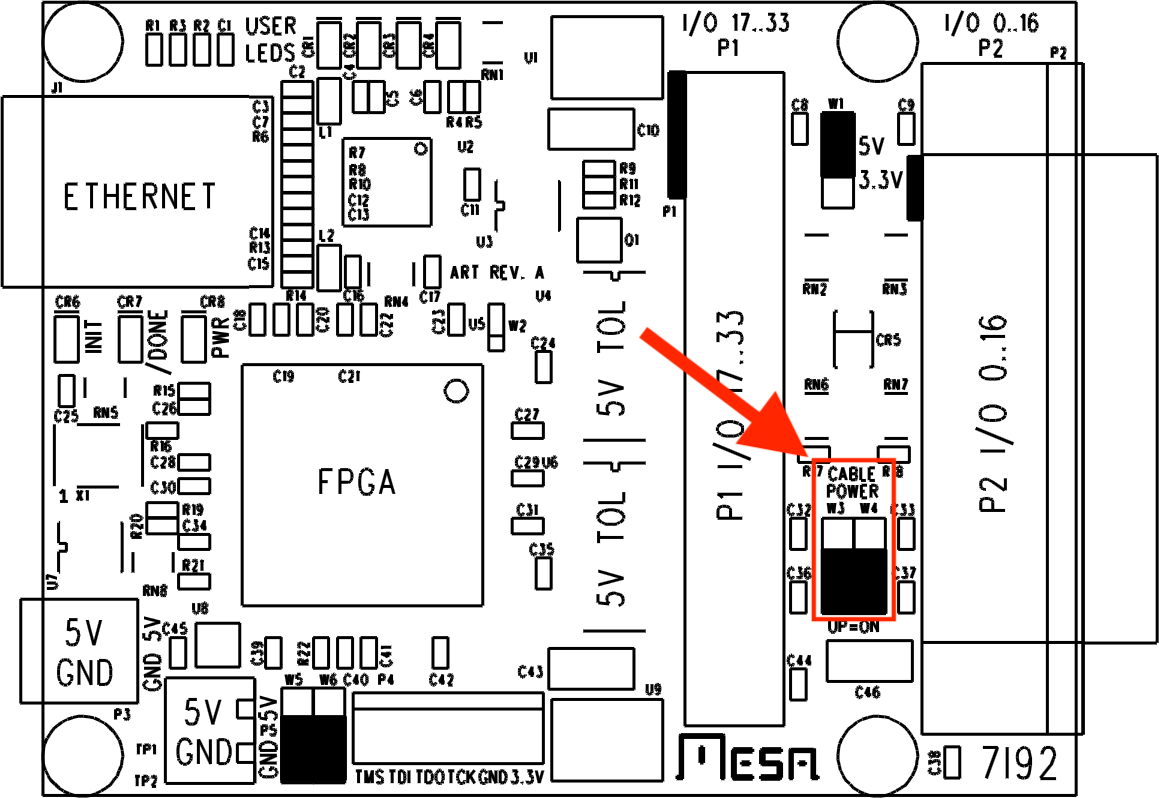 W4 jumper location |
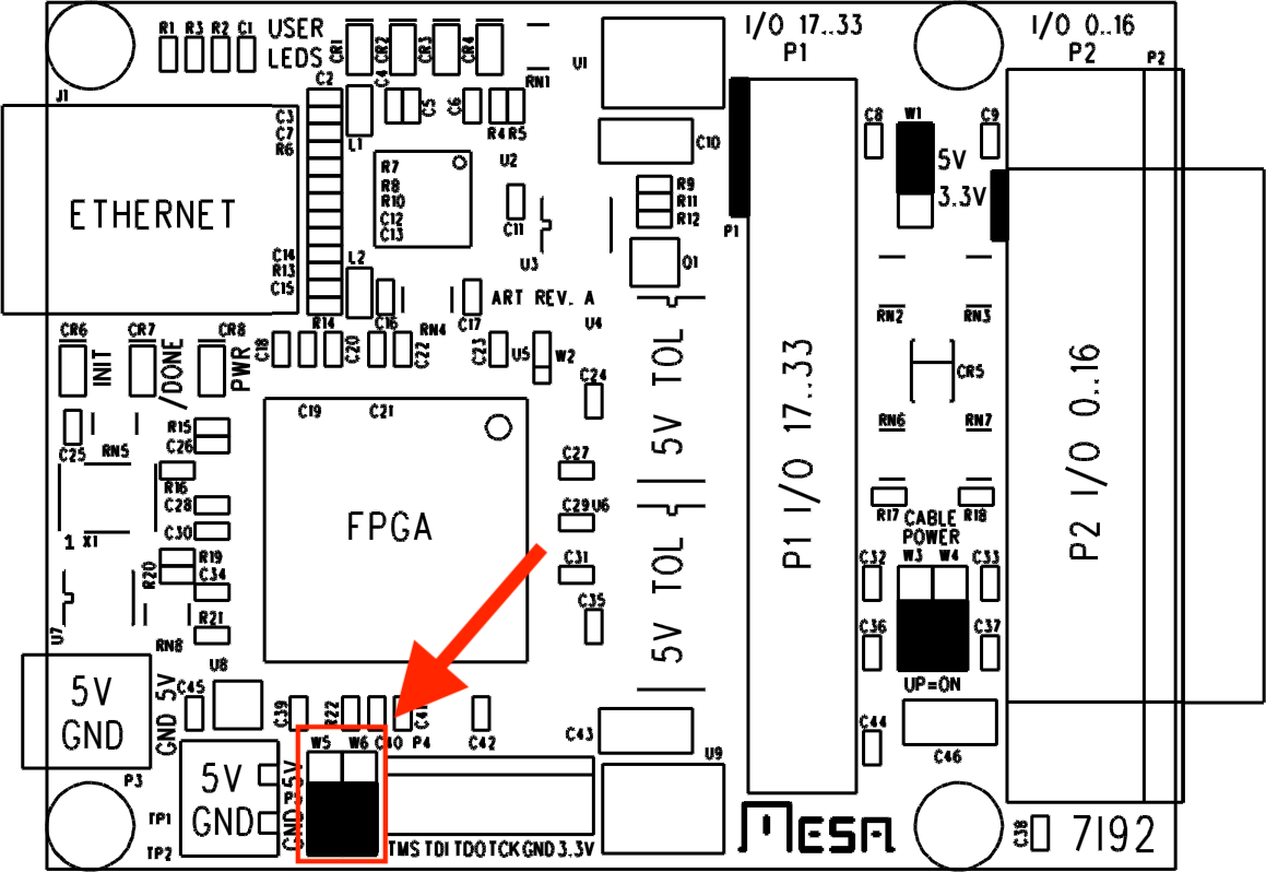 W6 jumper location |
- Leave the W5 and W6 jumpers at their factory setting (both down). The card then answers at its factory address, 192.168.1.121.
- Label each card Base or Expansion before it goes into its box. The two cards are set up the same way, but are given different addresses.
- The firmware, the address and the jumper change are done during the software setup, which tells you when to move the jumpers.
|
|
Next: Software Installation and Setup
|
eMail comments to |