
Cable Wire Color Scheme for Axes (Not spindles)
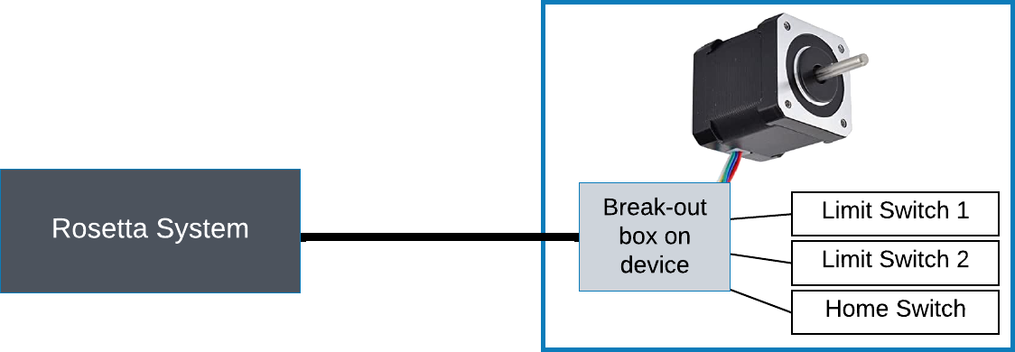
Cabling a device to the Rosetta System
The Rose Engine Butler system cable wire color scheme is outlined in the table below.
This follows the overall scheme as outlined to the right.
Note: This scheme is not used for the Spindle or the Rosette Phaser/Multiplier.
Cable Sizing
The cable between the Rose Engine Butler system and your device should be a 6-conductor cable. Even if you are not looking to use limit switches at this time, it is recommended that a 6-wire cable be used.
The connector cables we supply have GX/16-6 female connectors on both ends. At the device end of the cable, the stepper motor will be connected to the first 4 pins on the GX/16-6 male connector, leaving the other two unused.
Using this approach will keep the the connectors and connecting cables consistent and will not require you to keep multiple sizes and types of cables around.
The wires in the cable should be a minimum of 20 AWG (gauge). This will ensure the wire can easily handle the amperage for the NEMA 23 stepper motors.
Wiring the Motors
|
GX-16 Pin |
Stepper Motor |
Limit Switch |
Comments | |
|
Stepper Online Wire Color |
Purpose | |||
|
1 |
Black |
A+ |
n/a |
If the motor is driving the axis in the wrong direction, swap the A+ and A- wires. |
|
2 |
Green |
A- | ||
|
3 |
Red |
B+ |
| |
|
4 |
Blue |
B- |
| |
|
5 |
n/a |
n/a |
Signal |
This is used by a limit switch for shorting to GND when the limit switch is activated (i.e., normally open). If there are more than 1 limit switches, then they need to be wired to be parallel. |
|
6 |
GND |
This is a common ground. | ||
| spacer line |
|
eMail comments to |